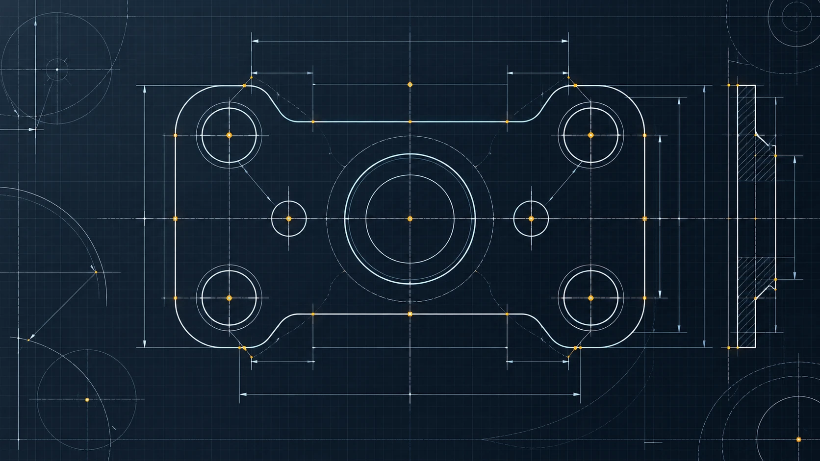
A line can look aligned on screen while its endpoint is slightly out of position. The difference becomes easier to spot after a measurement, an edit, or a file exchange. Precision comes from choosing a reliable way to place each point.
RLabCAD gives you several ways to do that. The grid provides visual reference, snapping helps locate meaningful points, and numeric input lets you state an exact value. They work together, but each solves a different problem.
Use the grid to understand spacing
The Grid control shows a visual reference across the canvas. The displayed step adapts as you zoom so that the grid remains readable.
That makes it useful for orientation and repeated spacing, but counting visible squares is not a dependable way to confirm a final dimension. The displayed spacing can change when you zoom. Your drawing geometry does not change with it.
If a line must have a specific length, enter that value or measure the completed line. Treat the grid as a guide to placement rather than proof of size.
Use grid snapping for regular layouts
The Snap control can constrain cursor placement to the adaptive grid when a closer geometry snap is not available. This is useful when laying out objects at regular increments.
Grid display and grid snapping are separate controls. You can show the grid without snapping, or turn grid snapping off while continuing to use the visible grid as a reference.
When a point appears to move in jumps, check whether Snap is enabled. A setting that helps with a regular layout can be inconvenient when you are trying to place a point between grid intersections.
Use geometry snaps to connect objects
For an endpoint that must meet an existing line, locate the actual endpoint rather than clicking approximately beside it. Geometry snaps help you target features such as endpoints, centers and intersections.
In RLabCAD, nearby geometry snap candidates take priority over the grid. That lets you connect to existing geometry while grid snapping is still enabled. Watch the snap feedback and confirm that the selected point is the feature you intended.
Zoom in when several candidate points sit close together. Zoom changes the view and can make the intended feature easier to distinguish; it does not repair a point that was placed incorrectly.
Type values when the drawing defines them
If you already know a point’s coordinates, enter them. For example, opposite rectangle corners at 0,0 and 100,50 define a 100-by-50 outline in drawing units.
The value expected by the terminal depends on the active command and its current step. A circle may ask for a center and then a radius. A rectangle may ask for two corners or allow dimension entry. Read the prompt before confirming a number.
For command-specific syntax, use the Rectangle reference and Circle reference.
Verify before adding detail
Use Distance to check important spans, and inspect object properties where a radius or coordinate matters. If a value is wrong, correct it before adding more dependent geometry.
A useful habit is to ask one question before each click: am I choosing an approximate location, a known feature, or an exact value? Use the input method that matches the answer. The Grid & Snap reference explains how the controls interact.